Beitrag-Spezial Landingpage Grundlagen New ropeways Technology

BASICS OF ROPEWAY ENGINEERING

Ropeway design principles

In response to a suggestion received from the ISR readership, we are publishing an ongoing series of articles devoted to the basics of ropeway engineering, which Professor Josef Nejez writes for those readers who have no relevant engineering background.

Created by Josef Nejez

In the last articles in our series on the Basics of Ropeway Engineering we looked at the items that are common to all ropeway systems. The question considered in this article is which ropeway system is suitable for which operating requirements and what the design principles of these ropeway systems are. (An overview of the various ropeway systems can be found in ISR 1/2018 und 3/2018.

Choosing the ropeway system

A whole series of criteria must be taken into account when choosing a ropeway system to meet specific operating requirements in a particular location. The principle items are as follows:

  • Function (e.g. cable car for winter sports)
  • Site factors (terrain, line length, vertical rise)
  • Transport capacity
  • Economics (capital costs, operating costs)

In addition, there are numerous additional considerations that can influence the choice of ropeway system (e.g. available plots for stations and tower footings, landscape protection, nature conservation, etc.).

Function of the system 

In this article, only passenger ropeways are considered. Material-handling ropeways differ from passenger ropeways primarily with regard to the types of carriers, which are designed specifically for the material to be transported (e.g. ore), and the associated loading and unloading facilities in the stations. In addition, the safety systems on such ropeways are simpler.

There is no standardized nomenclature to differentiate between passenger ropeways operated as recreational facilities on the one hand and as public transport services on the other, although the terms

  • tourist ropeways/cable cars and
  • urban ropeways/cable cars

are common. The distinction between the two can in any case be blurred. The Hungerburg funicular in Innsbruck, for example, is operated both as the first stage of the recreational installations serving the Nordkette mountains and as a public transport service linking the residential area on the Hungerburg plateau and the city centre (Fig. 1).

Tourist ropeways: The majority of all passenger ropeways are tourist facilities. The choice of ropeway system will be influenced by the purpose of the ropeway within the tourism region and the category of persons to be transported. The following basic distinctions normally apply:

  • Pedestrians including persons with reduced mobility: for this group of passengers, the ropeways must operate with enclosed carriers (funiculars, reversible aerial trams, continuous-movement gondolas)
  • More athletic pedestrians: in addition to ropeways with enclosed carriers, chairlifts are also suitable for this group
  • Winter sports passengers on skis or snowboards: for this category of persons, chairlifts with suitable loading and unloading points or surface lifts are required

In the mountainous regions of many countries, winter tourism is the primary source of revenues for ropeways. Depending on their function within the ski area, a distinction can be made between feeder ropeways (from the resort in the valley up to the slopes) and what are known as repeat-ride installations. Feeder ropeways usually have enclosed carriers, while repeat-ride installations tend to be chairlifts or surface lifts.

Urban ropeways: The term is used to describe installations that are situated at least in part in the urban area and are used to provide local public transportation services. An urban location alone is not enough; the public transport role must always apply if a system is to be considered an urban ropeway. In particular, urban ropeways – in the narrower sense of the term – are mainly used by local inhabitants, especially for travel to and from the workplace, and not just by tourists. In the ideal case urban ropeways are operated within a joint tariff system together with other modes of public transport (local rail services, undergrounds, trams, busses).

There is a logic behind this strict definition of the term “urban ropeway”, as there are significant differences in the demands made of urban ropeways  on the other hand and tourist installations on the other in terms of availability and operating hours: Urban ropeways must normally be designed to guarantee about 99.5% availability, while operation will typically be up to 20 hours a day and 365 days a year.

A basic article on urban ropeways can be found in the ISR special published on the occasion of the 10th OITAF World Congress in Rio de Janeiro in 2011 (https://de.isr.at/magazin-archiv/2011/2011-oitaf), p. 22, in which the terminology and the ropeway systems used are described in detail.

Site factors

The topography of the terrain on which the ropeway is to be built can have a significant influence on the choice of the system.

Funiculars with conventional cars require a fairly regular angle of slope so that the gradient of the track does not diverge by more than ±20% from the average gradient for the line, although bridges or tunnels can be built – at a price – to avoid excessive changes in gradient. Another possibility is to use cars in which the compartments are suspended in an outer frame so that automatic leveling can be provided (see Fig. 1).

For installations in precipitous terrain combining steep lines with significant vertical differences, the solution in many cases will be a reversible aerial tram (see Fig. 2). With convex terrain profiles especially, fewer towers are required, and rope spans over long distances and at considerable heights above ground are possible. The station structures are short and have a comparatively small footprint.

For long and relatively flat installations, the continuous-movement gondola lift is the system of choice. The main reason for this is the fact that transport capacity is independent of line length in circulating systems (see next section). The vertical rise in the line, on the other hand, is limited for technical reasons, and such installations have to be built in two or more stages where the vertical rise would otherwise be excessive. The station structures are relatively long and occupy a comparatively large area on terrain with no more than a slight incline due to the length of the horizontal acceleration and deceleration sections (see Fig. 3).


Due to the restrictions on maximum height above ground, chairlifts require terrain with a fairly regular angle of slope, as the catenary curves must be calculated with reference to the contours of the terrain. With regard to the station structures, the same applies to detachable chairlifts as to continuous-movement gondolas; fixed-grip chairlifts can be built with a considerably smaller footprint.


Surface lifts are even more dependent on a regular angle of slope as changes of gradient in the track need to be kept to a minimum. The haul rope should run as parallel as possible to the track so that the angle of the tow ropes and thus the T-bars or platters (and also towing force)  remain fairly constant during the ride. The station footprint can be kept very small.


Transport capacity

The transport capacity of a ropeway is the maximum number of passengers that can be transported per hour and direction. A key parameter in the choice of the ropeway system, it is determined by the following factors:

  • Capacity of the cars
  • In the case of reversibles, the number of return trips per hour
  • In the case of circulating (continuous-movement) systems, the carrier interval

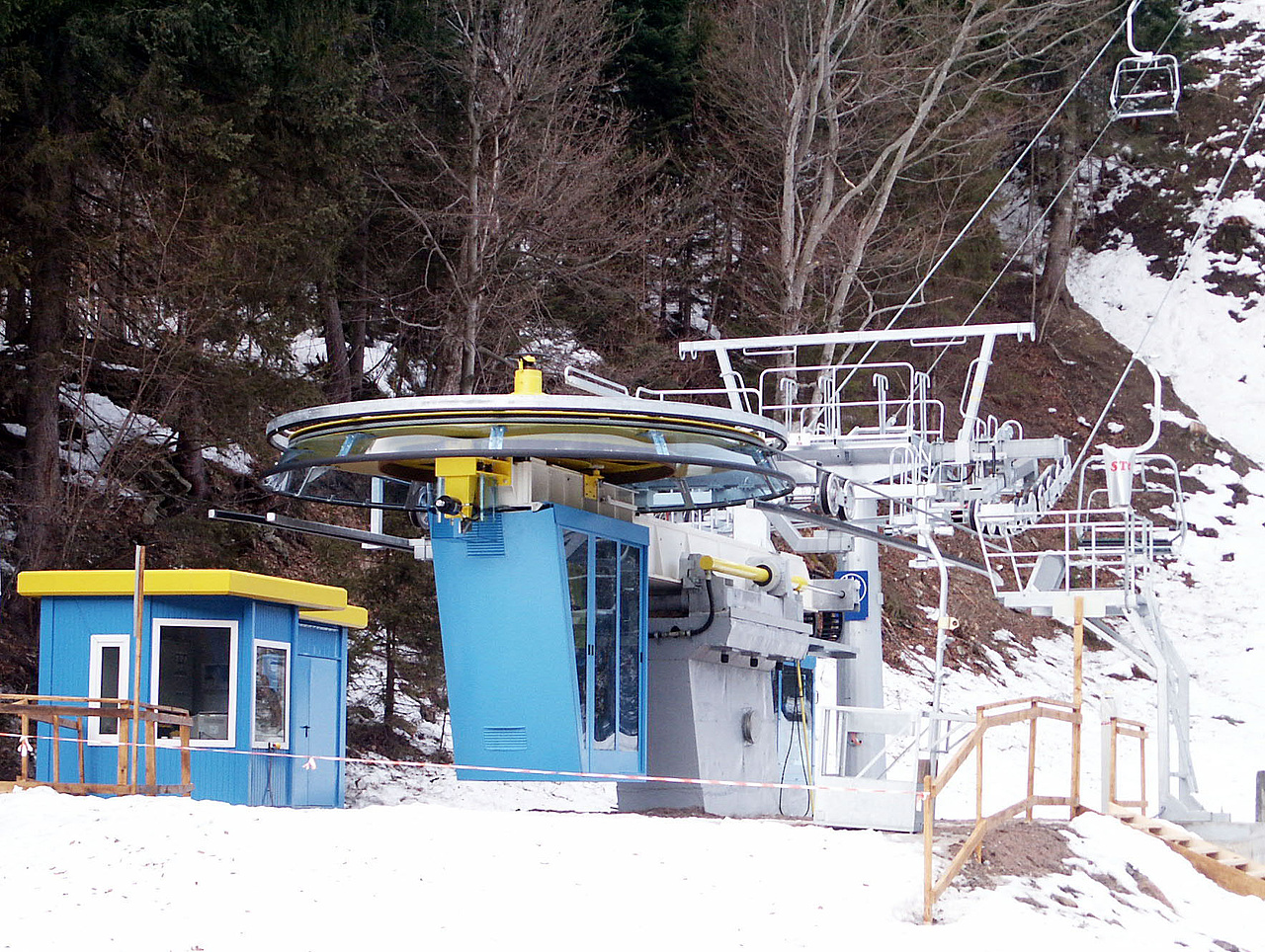
Reversible aerial trams: The maximum number of return trips per hour is dependent on what is called cycle time. Cycle time is the length of time between two successive carrier departures from a station. It is the sum of transit time between the stations and carrier dwell time in the station. Cycle time is expressed in seconds.

Transport capacity per hour and direction is the product of the number of return trips per hour and the capacity of the carriers.

Here is an example:

Assuming that transit time between the stations of a reversible is six and a half minutes (390 s), dwell time in the station 50 s and the capacity of the carriers is 80 persons (p), the number of return trips per hour is 8.18 (3,600 : (390 + 50) = 8.18) and transport capacity is 654 (8.18 x 80 = 654) persons per hour and direction (PPHPD), usually only specified as PPH.

Transit time depends mainly on the length of the line: Transport capacity decreases with increasing length of the line. In terms of transport capacity, reversible aerial trams are therefore best suited for ropeways with short lines.

Continuous-movement gondola lifts: The time that elapses between the departure of two successive carriers from a station is known as the carrier interval. It is calculated as the quotient of carrier spacing on the rope and line speed and expressed in seconds (s). The carrier interval must be long enough to permit safe loading and unloading as well as reliable operation of the safety systems as the carriers travel through the stations. For circulating ropeway systems (gondola lifts, chair lifts, surface lifts), the ropeway standards directly or indirectly specify minimum values for the carrier interval.

Calculating transport capacity: The number of departures per hour is calculated by dividing 3,600 s by the carrier interval. Transport capacity per hour and direction is the product of the number of departures and carrier capacity.

Here is an example:

Assuming that a six-seater chairlift has a carrier interval of 10.0 s, the number of departures per hour is 360 (3,600 : 10.0 = 360) and transport capacity is 2,160 (360 x 6 = 2,160) persons per hour and direction (PPHPD), usually only specified as PPH.

Here is another example in more abbreviated form:

Assuming that a surface lift with T-bars (2 persons) has a carrier interval of 6.0 s, transport capacity is calculated as 3,600 : 6.0 x 2 = 1,200 PPH.

Unlike a reversible system, the transport capacity of a circulating system is independent of the length of the line. For this reason, continuous-movement ropeways are needed to achieve high transport capacities on installations with long lines.

Vertical transport capacity in the ski area

In addition to ropeway capacity expressed as persons per hour transported (PPH), ropeway transport capacity relative to the vertical meters served for skiing or snowboarding etc. in the ski area is often formulated as vertical transport meters per hour (VTMH), which is the product of ropeway transport capacity and vertical drop. This is a useful parameter for an assessment of total ski area ropeway capacity as it makes a difference whether a ride gives access to a short slope with just a few meters of vertical or a long trail with a significant vertical drop.

Economics

Assessing the economics of a ropeway project is not usually one of the primary tasks of the ropeway engineer. The estimated capital and operating costs considered in the light of the overall financial situation of the ropeway company will often play a role, however, as will the use of methods for selecting alternatives (e.g. different ropeway systems) and variants (e.g. different lines for a given system). The main types of analysis performed in this context include the following:

  • Impact analysis
  • Cost-benefit analysis
  • Cost-effectiveness analysis
  • Cost-utility analysis
     

When comparing different ropeway systems or evaluating project variants, a cost-utility analysis, for example, can have a positive effect on the transparency and accuracy of the decisions reached through the focus on the weighting and evaluation of the criteria applied.

Josef Nejez


Photo: Andre Schoenherr

Swiss expert Laurent Vanat will unveil his analysis during Mountain Planet, one of the world’s leading trade shows for the mountain industry, which…

Read more
Photo: Überall

From the 6th to the 9th of May 2025, Messe Innsbruck will once again be the hotspot for the international ropeway and alpine technology industry and…

Read more
Photo: Doppelmayr

The next step taken by the Doppelmayr Group in autonomous ropeway mobility is "AURO" for chairlifts. The ropeway authorities in Switzerland and…

Read more
Photo: Doppelmayr

In the Mexican city of Uruapan, a 10-passenger gondola ropeway with a line length of 8.4 km and a rated capacity of 1,500 pphpd is now under…

Read more
Photo: Verlag Grada Publishing

In his latest book, the prominent Czech journalist Martin Harák, who has published many books and countless articles on the subject of railways and…

Read more

How XR, AR, VR and MR will change the travel experience of the future.

Read more
Photo: Pixabay

“Ropeways – Smart Transport Solutions” is the motto of OITAF’s 12th International Congress for Transportation by Rope, which will be held in…

Read more
Photo: Adobe Stock

Kelly Pawlak, President of the National Ski Area Association – NSAA, speaks about record capital investments in infrastructure, inspiring people to…

Read more
Photo: Skistar

In September 2022 the Swedish Skistar Group opened a 9,000 m² artificial ski slope on Hammarbybacken in the center of Stockholm using mats specially…

Read more
Photo: Skistar

NEVEPLAST/SKISTAR In September 2022 the Swedish Skistar Group opened a 9,000 m² artificial ski slope on Hammarbybacken in the center of Stockholm…

Read more

ISR Newsletter

Latest news relating to ropeways and winter destinations on your screen!

The most important news and reports about themes like ropeways, ski resorts, piste preparation, snowmaking and a lot more.

Subscribe now and stay in the know! Our bilingual Newsletter comes in German and English or German and French!
 

Subscribe

Subscription & Media Data

SUBSCRIPTION

MEDIA DATA